Alisam Engineering makes a Dremel holder for the South Bend lathe lantern tool post. I decided to make a similar holder. It would have been useful for grinding the point on the punch part of the bell center punch.
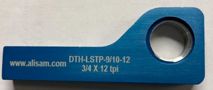
Like the Dremel clamp I will use a threaded bushing instead of threading the part directly. Knowing one measurement from the website I was able to estimate the other dimensions. The height of the stem is 5/8" per the website. The overall length is 4". The height of the Dremel holding end is 1 5/8". The width of the flat above the hole is 1 1/16". I estimated the angle to be 45°.
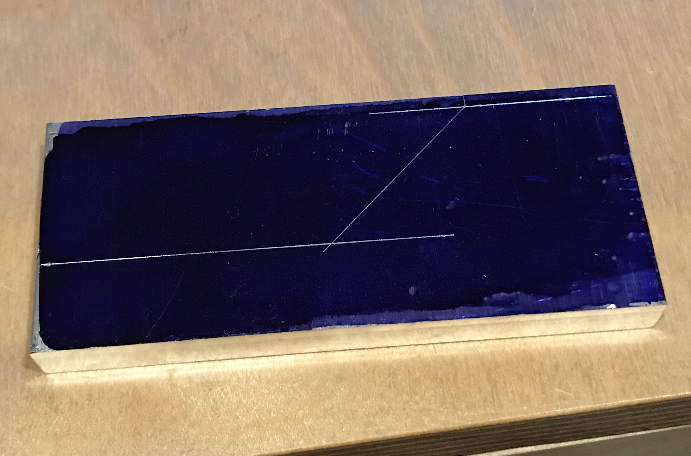
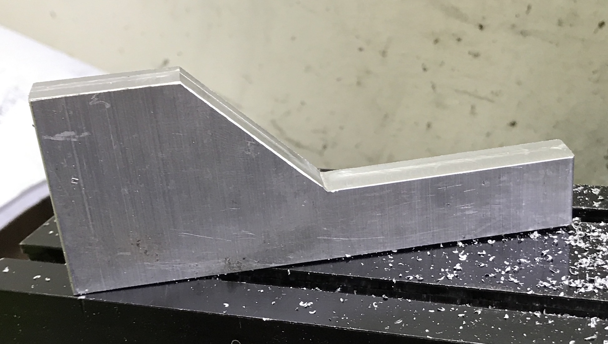
I just happen to have a 3/8" thick and 4" wide slab of aluminum. I cut off 1 3/4" with the band saw. I milled one side flat and perpendicular to the finished edge of the aluminum. The aluminum was painted with bluing dye. The measurements were laid out as shown in the photo below.
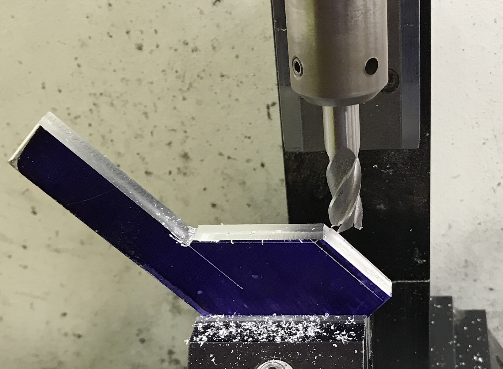
The angled piece was removed with a hacksaw fairly easily. The bottom of the part was set in the milling vise on parallels. The top of the flat was cut to the line in 0.015" increments with a 3/8" end mill. The part was then set at a 45° angle with a combination square. The angled side was cut to the line. Finally, the part was returned to rest flat in the vise and the top edge was cut. The burrs were removed with a small file and the inside corner was lightly filed with a round needle file.
I plan to set the height of the hole by clamping the part in the lantern tool post and then scribing a line with a center in the headstock spindle. I am not sure which washer I will use under the part. The smallest washer, the original, is too small. Setting two 9/64" drill bits on this washer puts the hole close to the bottom, but acceptable. The screw is not long enough for a lower setting! I guess I should have made the width 3/4" instead of 5/8". At any rate a 0.425" washer is required.
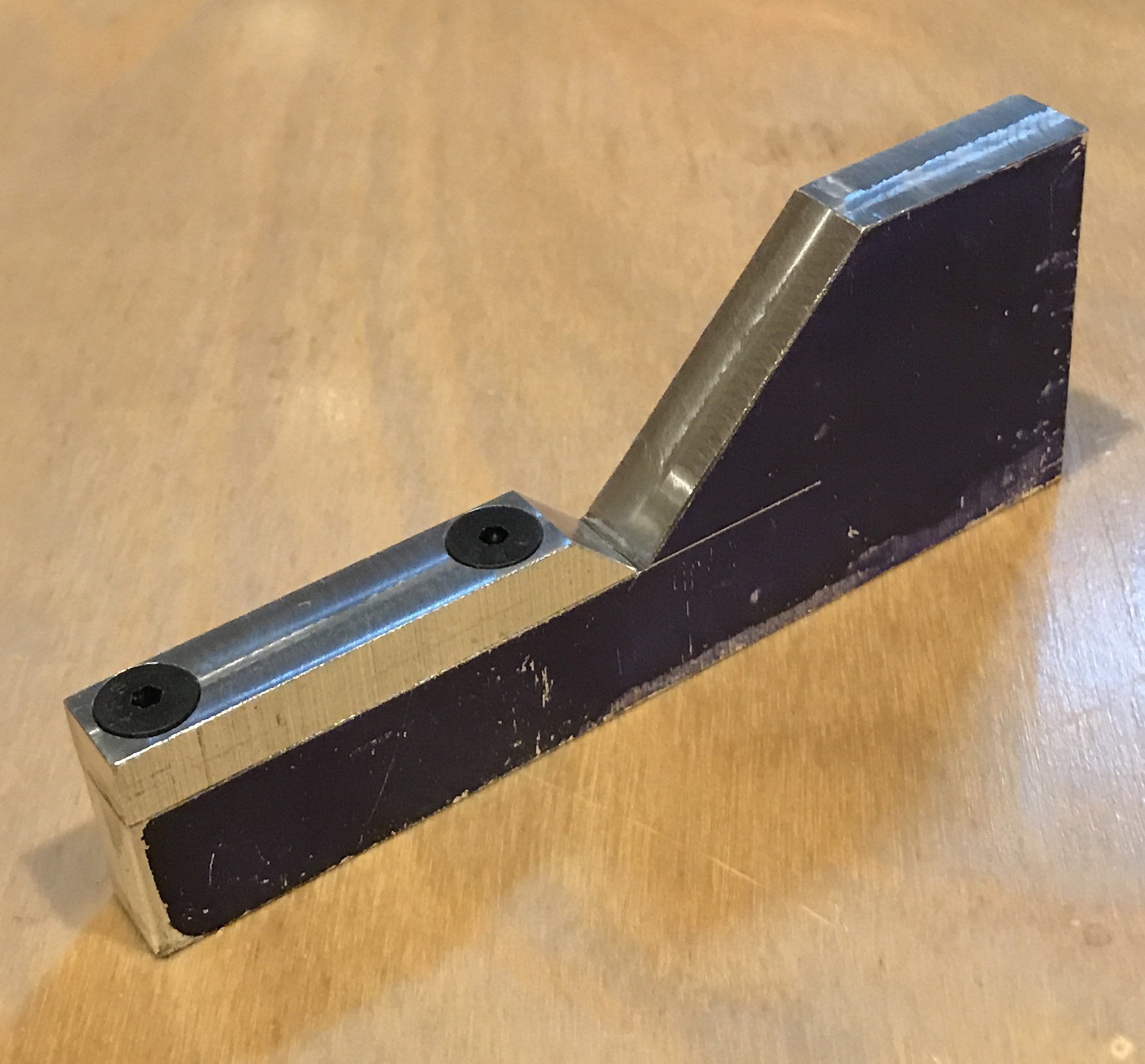
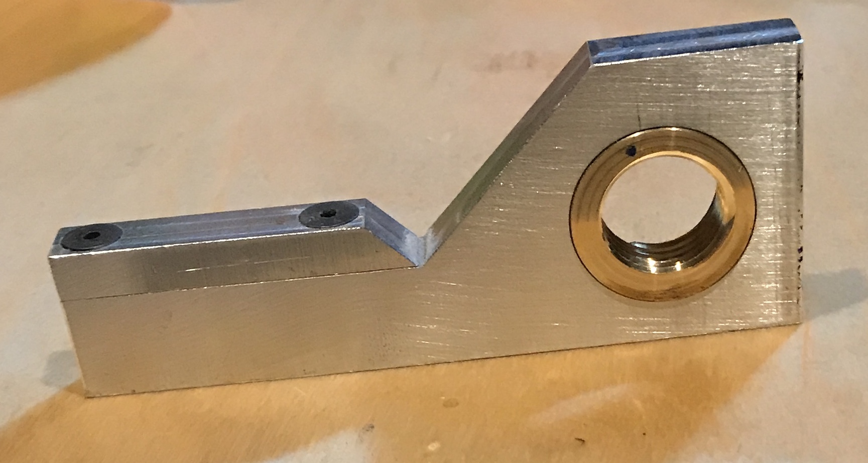
Second thoughts after a night's sleep. Raising the holder implies the hole is lower. If the holder is raised 1/8" as suggested above the hole for the insert is now only 1/8" or so above the bottom. This is too close for comfort. Instead I am going to add a 1/4" piece to the top. This was done by first squaring the side of the cutoff from above. The 1/4" high part was cut off with a hacksaw. The part was set on parallels and squared in the mill. The pieces were clamped together with a machinist's clamp. The parts were then drilled for a screw close to the middle of the two joined parts. The hole was drilled with a center drill and then with a #29 drill to a depth of 0.64". The first 0.25" was opened with a #17 drill. The tap was started and a few 8-32 threads were cut. The tap was removed and a countersink was used to deeply countersink the hole. The parts were separated and the tapping was completed. A screw was installed and the second hole was made the same way. Finally, with two screws installed the end of the new piece was trimmed flush with a 3/8" end mill. The photo shows the completed budgie job. The holder was installed in the lathe and the height marked with a center in the headstock.
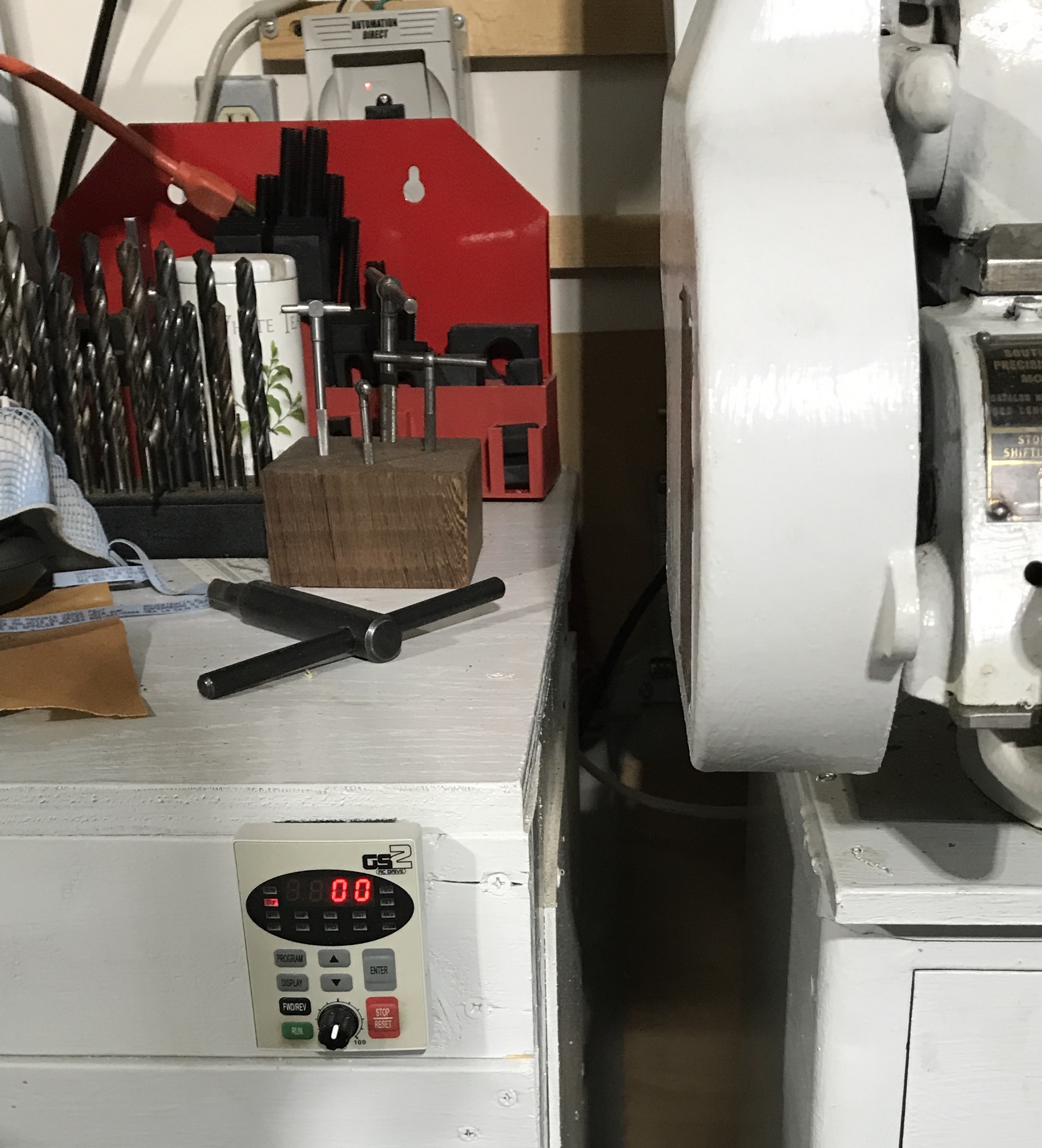
A slight detour in effort this morning. The cable arrived for the inverter. Of course, it attaches to the back of the controller, so to mount it a hole had to be drilled in the cabinet. A large hole! Through a 2X4! The batteries were dead in the cordless drill so I pulled out Heshe's old drill. A 1 5/8" Forstner bit was used. After about 30 minutes I had forced my way through the cabinet frame. A similar hole was drilled in the 1/4" thick back in a minute or two. The cable was snaked through the cabinet and attached to the inverter and to the controller. Works perfectly. I will no longer need to reach around the lathe and over the cabinet to turn the lathe off! The photo below shows the controller velcro'd to the cabinet. The inverter can be seen against the wall.
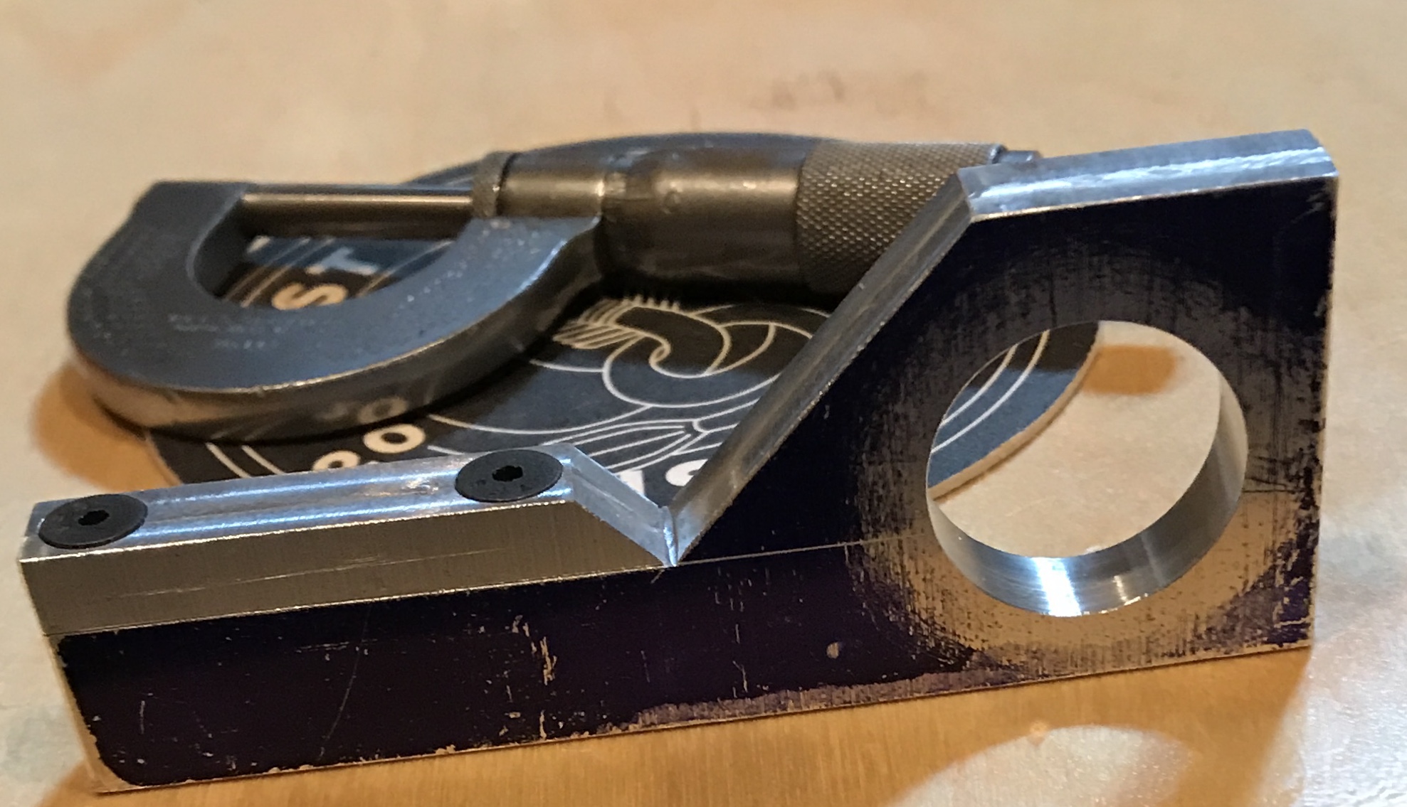
The location of the hole center was marked and punched. It is centered 3/4" from the end. The holder was aligned in the four jaw chuck on the South Bend lathe. One jaw had to be reversed. The hole was drilled with a center drill and then up to 3/4". The hole was opened by boring to 0.995". The photo shows the result.
I found a scrap of 1" brass round bar that was 0.413" long and had a 3/8" hole in the middle. The scrap was faced on the rough side. A mandrel was made from a second scrap of 3/8" hex brass. It had a 3/8" round end, which fit nicely in the hole. The end was drilled with a #25 drill and threaded 10-24 because I had a flat head 10-24 screw. The hole was threaded and then chamfered deeply for the screw head to apply the expansive force. The screw was cut to length. The end of the mandrel was cut with a hacksaw to produce four slots. Everything was cleaned up and the mandrel held the brass part tightly. The brass was not very concentric on the mandrel, but its diameter was reduced to 0.995".
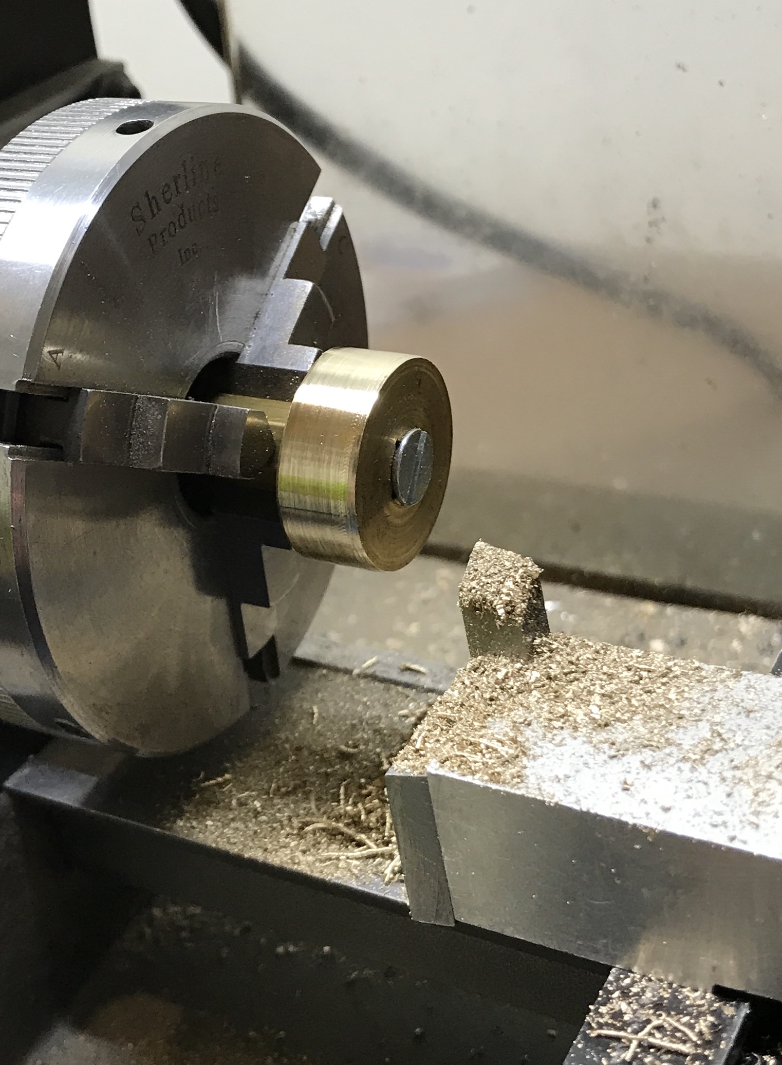
The brass insert was bored to 0.665" as measured with the aid of a hole gauge. The Sherline lathe was set up for threading 3/4-12. With a lot of effort the threads were cut to a depth of approximately 0.063". I don't think the threading tool can cut any deeper. The threading was challenging because the gear train came loose on three occasions! It is a tight fit on the Dremel, but it fits! The aluminum part was sanded on the two faces with 220-grit sand paper. The brass was then pressed into its mating hole to complete the Dremel tool holder.
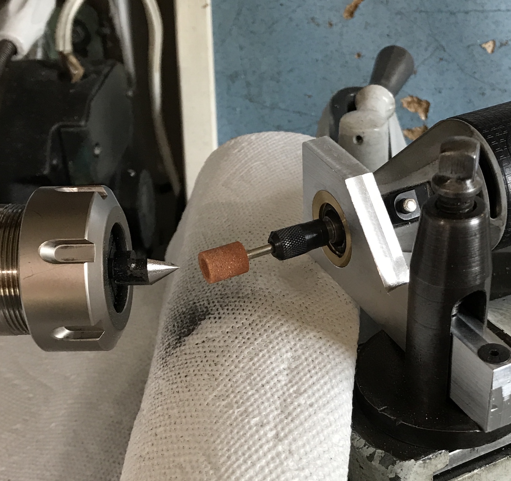
The holder was tried out this morning. The compound was set at 30° and the Dremel was aligned with the compound. A tailstock half center was held in a 1/4" collet. The grinding wheel was run past the center in 0.002" increments. The Dremel rotates counterclockwise as seen from the end. The lathe also rotates counterclockwise. I would expect that one rotating in the opposite direction would be preferred, but have no data to back this up. A paper towel was used to catch the dust. Probably not the wisest choice using paper to catch red sparks. The grinding went well. There was significant high speed chatter as can be seen in the finish. It is not clear if this is due to rotation direction, speeds and feeds, flex in the tool, or the interrupted cut. The photo shows the setup after grinding.